![]()
|
|
Personal web pages ofTim Stinchcombe |
|
This page details modifications to the M38A ADSR Expander module (which adds voltage control to the ADSR)—if you are looking for the mods for the M38 ADSR module itself, they are here. The mods for the M38A Expander module on this page assume that the M38 ADSR to which it is attached have had the above mentioned mods made to it! Plan B M38A ADSR Expander modificationIf you changed the jumpers on an M38, hooked it up to an M38A Expander module, and then spent a few minutes twiddling the pots on the M38, you could be forgiven for thinking that the M38/M38A combo just doesn't work, as you are likely to either get virtually no envelope whatsoever, or it will quickly rise to (what appears to be) the +12V rail and stay there until the gate is released (and that is assuming the M38 has been previously modded—if it is an unmodded one it may well be even harder to get anything out of the pairing at all). It was only at my second sitting with the module that I managed to get anything at all, and it was of the 'shooting to the rail' type envelope I achieved (this is whilst using the pots on the M38 to control the envelope, rather than feeding CVs into the M38A, though in that case the situation with the sustain level is largely unchanged):
Oddly enough the difficulty in not being able to get a normal envelope arises from a similar problem to the M38—a missing/misplaced resistor—and just as with the M38, it is hard to imagine how Plan B thought the M38A was a viable module given this major shortcoming. At this point it is worth pointing out that the envelopes that the M38 is capable of producing are perhaps somewhat unconventional, in that as well as the normal decaying downwards to some sustain level after the end of the attack phase, the sustain level can be set higher than the end of attack, so that the envelope in fact continues to climb toward the sustain level. The missing/misplaced resistor means that the sustain level is always set at its maximum level, hence the envelopes in the above set of traces being so 'tall'. Correcting for the missing resistor is easy enough, and is detailed in the next section; however that is not the whole story, as there are other facets of the design which require additional changes in order to make the whole make sense—these are also given in the following section, and because the reason for these changes is not that evident (they could have been avoided altogether if it were not for a poor design choice in the original design), a later section explains how some of these problems arise. The modification. Compensating for the missing/misplaced resistor in the M38, and so gaining control of the sustain level, is easy enough, and is effectively accomplished by moving a resistor: replacing one resistor with a wire link, cutting a track, and bridging the cut with a new resistor—this new resistor will be designated as 'Rx'. Taking the value of Rx to be that of the equivalent resistor on the M38 (100kΩ) will give the 'standard' sustain CV control range that the M38, and the M38 paired with an M38A, were designed for, but some may see this as non-optimal—choosing a different value for Rx, in conjunction with the value of resistor R3, gives several different control possibilities, of which some of the more obvious ones are now explored. If we take Rx to be 100kΩ, and leave R3 at its default value (presumed to also be 100kΩ—I have only ever seen a single M38A!), then we get a sustain level that varies from 0 to about 10V, which is controlled via a CV of the same size, i.e. from 0 to 10V (note: the diagrams that follow are based on simulations—I didn't literally try all combinations shown—so in reality there will likely be small discrepancies; they show multiple envelopes overlaid on one another, and for just the attack and 'decay' phases; to get precise control of the levels using the sustain CV, the sustain pot on the M38 needs to be fairly precisely placed, generally in the higher part of its rotation, i.e. from about half-way through to fully clockwise):
(If the sustain level being greater than the end of attack still seems strange, take a look at this short note about the M38 sustain levels!) Some standard Eurorack modules may struggle to produce CVs that go as high as 10V (e.g. other envelope generators may only go to 5 or 6V, similar to the levels output by the M38 itself for a 'normal' envelope), so in order to sweep the sustain level through its full 10V range with a CV of only up to 5V, choose R3 as 47kΩ (and Rx as 100kΩ):
In the first option (R3 & Rx 100kΩ), the 'flat-top' envelope requires a CV of around 6V to achieve, which suggests another option would be to have this occur at a CV of 5V instead, and greater voltages would still give the taller envelopes (with the 10V maximum achieved with a CV of around 8.5V)—this is achieved with R3 as 82kΩ and Rx 100kΩ:
If we wish to dispense with the taller envelopes completely, and restrict them to just be 'flat-topped' or lower, make Rx 160kΩ—with R3 as 100kΩ, we control these with a CV range of 0 to 10V again:
There are several things to note here. First, if we use 180kΩ, it may not be quite possible for a maximum-input (10V) sustain CV to actually give a 6V flat-topped envelope—it may fall a little short (as the diagram in fact, which was drawn using 180k, and I couldn't be bothered to re-draw it when I decided to change to 160k!). Secondly, changing Rx to 160kΩ will also limit the height of the available envelopes when using the sustain pot on the M38, though if the M38 were used stand-alone again, it would still give the taller envelopes (because we are not changing anything in the M38!). If you like the idea of limiting the envelope height, but want to control it with sustain CVs up to just 5V, pick R3 as 47kΩ, and Rx as 160kΩ:
The following table summarizes the choices for R3 and Rx:
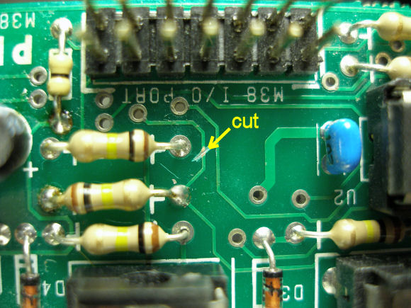
So, to the changes themselves. Here is the track that needs to be cut:
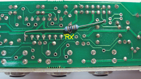
The cut is bridged on the other side of the board with the insertion of 'Rx', of the value chosen from the above diagrams/table (100k shown): carefully solder the resistor in-between the points shown (a via near the header, and pin 14 of U2):
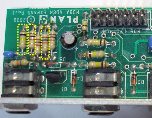
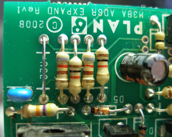
(With the body of the added resistor positioned as shown, the chances of it making an unwanted short to anything else should be minimized, but if in doubt, add some sleeving over the resistor leads!) Replace the two highlighted 1kΩ resistors with 820Ωs; replace the 100kΩ (R22) with a wire link (or short across the bottom with a wire link):
(R22 is the resistor which is 'moved' to become Rx; for those curious enough to want to know, the reason for the 1kΩ to 820Ω changes is outlined below.) So when modified it should look like this:
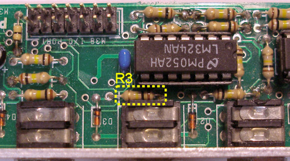
As determined above, resistor R3 impacts the range of effect that the sustain CV voltage has on the sustain level, and if it is decided it is to have a value other than the default of 100kΩ, then it will need changing—here is its location, directly behind the 'sustain' jack
M38 trimpot adjustment, front-panel pot settings during CV operation, and envelope timings. To protect a key chip in the M38, circuitry controlling the A, D and R rates has a built-in limiter to prevent a current getting too big, and this means there is a maximum rate for the A, D and R phases of the envelope. In a (modified) M38, the purpose of the trimpot is to optimize when the current comes off the limit, so that no front-panel pot travel is wasted—as soon as the pot comes off the full counter-clockwise stop, the appropriate phase will start to slow down, so this means we get the maximum range of fast, through to slow, envelopes. Similar to the problem of the missing/misplaced resistor for the sustain circuitry, there are three other misplaced resistors (one each for attack, decay and release): whilst they aren't nearly as catastrophic as the sustain problem, they do have a 'scaling' impact on the circuit's operation, and this affects the trimpot setting when an M38A is hooked-up to the M38. I think it unlikely in normal use of an M38/M38A pairing that anyone would notice these differences over an M38 when operated stand-alone, so I elected not do anything about them—it would have required either loads more track cutting and adding of extra resistors, or potentially having different mods to the M38 depending on whether it was going to be used with an M38A or not (I say 'potentially' as I haven't been bothered to study it in any great detail). Unfortunately I then discovered that convincing myself of what to do with the trimpot seemed to be rather difficult, due to the differences between CV control and pot control, and their interactions. The (rather busy it has to be said) table that follows attempts to summarize a lot of the readings I took whilst doing this, but before we go any further, here is my recommendation for the trimpot setting on the M38, when used with an M38A Expander: - simply set the trimpot fully clockwise. The table shows the fastest and slowest envelope timings, for the attack phase only, for a large number of different settings: only the attack is given due to the difficulty in saying when the envelope 'completes', especially for really slow ones (the gate is just held open with a constant high voltage, and since we are not considering release at all, its pot was always fully counter-clockwise). Readings are split for control of the envelope using either the front-panel pots only, or by applying a control voltage via the M38A; for CV control, as soon as a voltage is applied, even if it is zero volts, due to the large DC offset voltage about which the necessary inversion of the signals is performed (this is detailed in the big section below), currents will start to flow, and generally some amount of front-panel pot will need to be dialled-in in order to compensate, and hence there are large differences in behaviour between a CV of zero volts and with the CV input floating.
Some explanation. Given the apparent simplicity of its design, I spent a disproportionate amount of time working out how to 'fix' the M38A Expander module, running many SPICE simulations, producing pages of algebra, calculations, graphs and diagrams, and taking many, many measurements from the real thing, and since I'm a strong believer in 'a little understanding goes a long way', I'm going to outline some of these considerations here. However, these are presented only because they are interesting in their own sake, or for their instructional value—it is not necessary to understand or even read this section in order to perform the above mods successfully! The difficulties are due to a number of factors: a poor design choice considerably hampers the existing design; having to work within the constraints imposed by this makes life harder than starting from scratch; and there are many resistors available to change, giving a huge number of combinations from which to chose from, and with numerous interactions between the functions involved, this makes it hard to find the right compromise between all the functions. The sustain level problem is caused by the 'breakout point' at which the sustain pot voltage is feed out of the M38 into the M38A and then back in again being in the wrong place. It is the wrong side of a resistor, so when the voltage comes back in from the M38A, the lack of the potential divider action that ought to be created by the missing/misplaced resistor leaves the voltage at way too-high-a-value compared to what it needs to be. Consequently there is no control over the sustain level, which is effectively permanently set at 'maximum sustain'. The effect of this is seen in the traces at the top of the page: the circuitry is arranged for 'end of attack' to occur when the envelope hits mid-rail, i.e. 6V, and then as mentioned above, even though the envelope could potentially go up as well as down, because of the missing resistor, regardless of the actual sustain pot voltage, the envelope always climbs until it gets to around 11V (the output 'saturation voltage' of one of the chips), where it stays until the gate releases. The two traces show that some variation in the 'attack' and 'decay' slopes is possible, but it hardly gives what one would consider to be a 'normal' envelope. Inserting a resistor at the correct place re-enables correct control of the sustain level voltage, but then we immediately run into another problem—the sustain level cannot be reduced below a certain voltage. This is caused by the baffling decision to not pass the −12V rail across to the M38A. The basic job of the M38A, for each of the four A, D, S & R functions, is to add a CV to the corresponding pot-derived voltage; in an op amp-based circuit, addition is most readily achieved using an inverting summer set-up, but this requires a second inversion in order to restore the correct sign-sense. We will concentrate on the sustain level processing, as that is where the major problem lies—the others (A, D & R) suffer similar problems, but have less impact, and in any case the exact processing is slightly different. To help conceptualize the processes involved, we appeal to some simple diagrams: the horizontal 'in' axis depicts the voltage input at the very start of the whole process; the vertical 'out' axis depicts the voltage output from each stage as we work our way down the stages making up the whole; we do not attempt to show any addition, just the inversions that this necessarily entails; the first stage is basically just a 'null' process, with 'out' equals 'in', and it is this relationship that we seek from the process as a whole (i.e. we do not wish the inversions of the addition to have any impact at all); the diagrams are kept (mostly) devoid of any sense of scale, in order to keep them simple. Thus for the ideal case of the process being able to handle both positive and negative signals, we see that the first inversion simple flips the voltage about the horizontal axis, and the second one does the same thing, returning us to where we started from, which is exactly what we require:
However without access to the negative supply rail, as in the M38A, we cannot have this simplicity, but if we perform the flipping operation of the inversions about the mid-rail point (readily achieved in op amp circuitry) which is what the M38A does, we can still achieve what is desired:
This is all fine in theory, but unfortunately things start to unravel because in practice, real-world op amps have limitations. The M38A uses LM324 op amps, which are well-known for their single-sided supply operational capability, and whilst their outputs can swing very close to ground (within a few tens of millivolts), they can only swing within about a volt or so of the positive rail. Thus at each inversion the output cannot reach as far as 12V, but instead 'saturates' at some level below this (around 11V or so, 'Vsat' in the diagrams), and this clipped level from the first inversion, once flipped by the second inversion, becomes a lower limit below which the signal cannot go:
Thus the sustain level cannot be reduced below this level. This is reasonably easily counteracted in the mods above by changing the resistors defining the mid-rail voltage about which the inversions flip—the 1kΩ resistors merely form a simple potential divider, and reducing the lower ones (to 820Ω) thus reduces the voltage, with the result the whole curve is offset downwards, thus removing this lower limit. The following set of traces show how the minimum sustain level changes as each step in the modification detailed above is applied:
This set of traces shows the range of the sustain level on the modified unit (Rx is 100kΩ) when it is controlled by the pots on the M38. Note that the maximum height of the envelope is now about 10V—this is because of the downward shift of the 'flipping level':
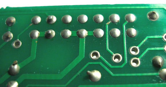
A warning! When I was looking for a hook-up point for one of the mod resistors, and saw that the 14-way header (apparently) wasn't properly pushed through the board, I assumed this example was just sloppily built, and so thought 'no problem, I'll just pop it out and insert a new one—properly!':
However, after having desoldered the joints, the reason for the connector not being through the board became abundantly clear—it was not because the connector was poorly inserted/built, it was because the holes in the PCB are clearly simply not big enough! Thus if you have one that also looks like this I strongly recommend leaving it well alone! It may not meet IPC-A-610 soldering standards—no 'witness marks' of the pins in the solder—but because the holes are too small and the pins do go most of the way through the board, the connector (at least on the example I saw) is well anchored to the PCB. Fortunately there is a via nearby which suffices to solder the mod resistor to. (Attempt to remove a connector soldered like this, and it will put up a fight, and probably take some of the through-hole plating with it!) [Page last updated: 29 Jun 2014] |
||||||||||||||||||||||||||||||||||||||||||||||||||||||||||||||||||||||||||||||||||||||||||||||||||||