![]()
|
|
Personal web pages ofTim Stinchcombe |
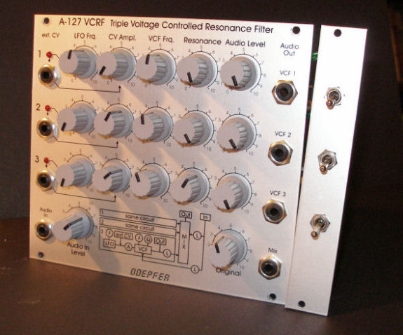
A-127 Switchable LP/BP Modification
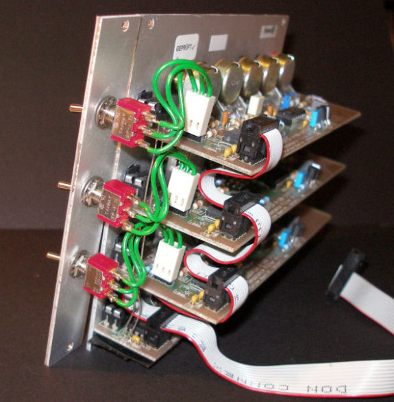
Each of the three filters in the A-127 can be switched between a lowpass or bandpass characteristic by repositioning a jumper on the respective filter circuit board: this is 'JP5' for 'version 3' of the filter (which I have), but is different for the earlier versions '1' and '2' (refer to the A-127 Owner's Manual). It is very straightforward to wire each jumper to a single-pole change-over switch so that the filter type can be switched back and forth at will: solder a wire from the common on the switch to the centre pin on the jumper (or use a suitable 0.1" pitch socket, as I did), then wires from the other switch contacts to the outer pins on the jumper. With care and small-enough switches it should be possible to mount these underneath the individual filter output sockets: I took the easy option and simply mounted them on a 4HP blank situated next to the module itself! [Page last updated: 07 Mar 2010] |