Personal web pages ofTim Stinchcombe |
|
In the early Seventies my old school was given an old analogue computer, a Solartron 'Minispace'—here is a photo of a similar example at the National Museum of Computing at Bletchley Park:
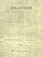
At the time the mathematics necessary to understand its use was completely beyond me and pretty much everyone else at the school, so it mostly just sat there doing nothing—we gave it the nick-name 'The Fruit Machine' for obvious reasons. On the occasions we did mess with it, it was clear some of the modules in it simply didn't work, and some of the others may have done, it was just that we didn't know how to make them do anything useful. I seem to recall there were at least two servo resolver units in it, one of which could sometimes be made to whiz around uncontrollably, and also a 'diode function generator', which had a slide-out control panel and was as intriguing as it was mysterious. I did however keep the few documents that we had that went with it, and since there is apparently something of a dearth of information on this particular machine on the internet, decided to scan them all when recently asked if I did have any information on these machines. So here are scans of three documents: they are from 'black on yellow' photocopies (which aren't all that bad, considering this was the early Seventies)—they are scanned as 300dpi 'greyscale', except for the SCD10 document, which is 600dpi to try and make the finer-detailed schematics more readable; the small thumbnails show the original yellow colour (and the PDF-writing software in my scanner seems to have auto-rotated some pages to make the columns vertical, hence the reason the page sizes are sometimes not uniform): Operational Manual for Minispace (10.8megs): 
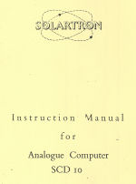
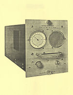
Instruction Manual for Analogue Computer SCD10 (7.4megs). (I'm not sure whether the 'SCD10' was a predecessor or successor of the 'Minispace', but the picture of it is very similar to a Minispace, which is presumably why the manual was part of the bundle of documents.) 
Servo Resolver TJ961 (seems to be a complete specification and operation manual for the module, 7.6 megs) 
The main patching area of the computer is apparently broken down into smaller sections, one each for the different amplifiers/modules, dependent on the actual fit of a specific computer. Here is a schematic/wiring diagram of part of the patch panel, with sections marked as 'amplifier', 'servo multiplier' and 'general' (considering there must have been many such drawings covering the model my old school had, it seems very random that we had this at all). The originals are about A4-sized; the yellow marks are from the sellotape that was holding them together; the drawing from which these are copies was also apparently a composite, showing joins in several places (scans at 300dpi, so each picture is over 1meg big): [Page last updated: 27 Apr 2013] |