![]()
|
|
Personal web pages ofTim Stinchcombe |
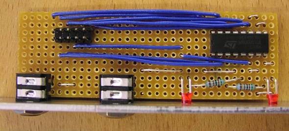
A-155 16-step ModificationFigure 6 in the A-155 Owner's Manual section shows a simple patch, using an A-160 Clock Divider and an A-150 Voltage Controlled Switch, to turn the 155 into a simple 16-step sequencer. Someone in the group suggested it might be a nice idea to make up a permanent 'adapter' to do this, and when I looked into it, it was so simple I made one up straight away! The 155 itself contains a '4024 counter which already provides the necessary clocking (which the 160 would do externally), and so the only other components required are an analogue switch chip and a couple of LEDs, plus resistors. The mod is (relatively) straightforward, and allows for permanent Trig and CV outputs to turn the 155 into a simple 16-step sequencer. I deliberately don't want to be too 'prescriptive', as what I have done is quite a lot more than really needs to be (for several reasons: I move my modules around a lot, so a separate 4hp plate with 10-way IDC + ribbon fits the bill; and I was too lazy to consider pulling various boards off the 155 to drill extra holes etc.). I used a piece of stripboard because I had some, and I more-or-less just added the wires as I needed to, cutting tracks where needed - the mod could be done by sticking the IC on its back and soldering directly onto its legs. Here is the schematic for the extra circuitry: 
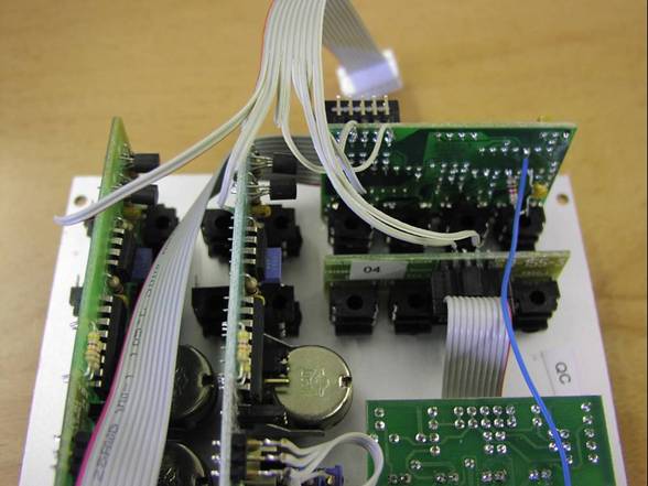
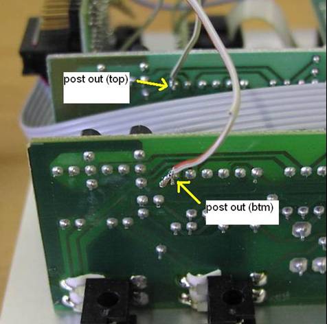
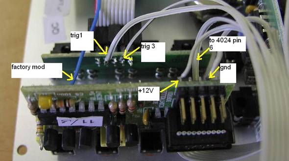
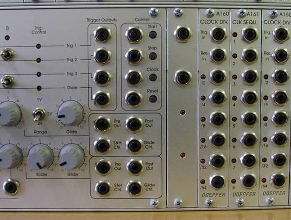
The chip is a CD4053 or something equivalent, such as an HEF/HCF4053 etc. Resistors could be 2k2 for use with 5mA LEDs (I used 5k1 as the LEDs I had were low-current 2mA types, left over from some kit I built). The following pictures show where the signals are picked off the 155:
Pin 6 on the '4024 is just that. There is no other connection to this pin on the board (the 4024 is right next to the other connector on the controller board). Trig 1 is the second pin down on the back of the connector on the 'trigger/gate adapter board'; Trig 3 is the second pin up on this connector (you can easily trace tracks to the sockets to be sure). There's no need for any sort of switch: when not in use there are no loading effects on the normal 8-step circuitry - when you want to go 16-step, just plug in! The only thing I haven't catered for is if negative voltages are input to the bottom row external inputs. Since I have taken Vee, pin 7 to ground, the 4053 will not be happy with such voltages (it's highly unlikely I will ever want to do this). If bothered about this, there are two 79L05s (one on each potentiometer board), and the -5V from either could be taken to pin 7 (the 4053s already in the 155 are wired that way). [Page last updated: 14 Dec 2009] |