![]()
|
|
Personal web pages ofTim Stinchcombe |
|
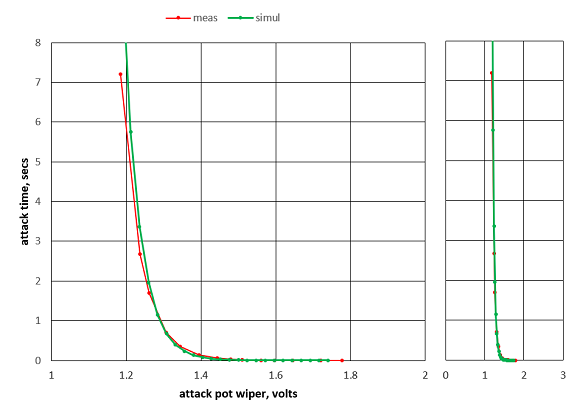
This page details modifications to the M38 ADSR main module—if you are looking for the mods for the M38A ADSR Expander module (which adds voltage control to the ADSR), they are here. Whilst writing up the mods for the M38A Expander module I decided it would be worth adding some comments here about the behaviour of the 'sustain' voltage level, which is not quite what one would normally expect of an ADSR. Plan B M38 ADSR modificationIt doesn't take long playing around with an M38 to realise just how completely intractable the control range is—most of the useful action from the attack, decay and release pots takes place in about 5% of their available travel. The following is a plot of the attack time versus the pot wiper voltage, over much of the range which produces a change:
That's a change from about 200μs to over 7secs in a little under a 0.6V change in the pot wiper—re-scaling the wiper axis to encompass its entire sweep from 12V down to ground (which more or less equates to turning the pot from fully CCW to fully CW) emphasizes just how little of its travel is being used:
(The 200μs is about as fast as mine will go; it will go slower than the 7secs plotted, but seeing how vertical that line is becoming, it gets even harder to control it, so I didn't bother taking any further readings.) It is so hard to control it is difficult to understand how Plan B even thought that in this configuration it was a viable module, and indeed, an old thread at the (now defunct) modularsynth.net forum acknowledged that it was problematic, and that around 25% of those sold at the time had resulted in comments from concerned buyers. The module I have is marked 'Rev 1' and dated 2008; they began shipping around the middle of 2008, and by Jan 2009 message #2412 at the Plan B Yahoo group further acknowledged that changes were needed (though the proposed change of pot type would have left the problem substantially unresolved [Jan 2018: I've added a new section about this at the bottom of the page]), and since Plan B effectively ceased-to-be around mid-2009, I doubt there are any other later revisions or changes to the module out there. (It is perhaps also worth noting that twiddling the trimpot doesn't have a great deal of effect on the issue—all it does is move whereabouts in the total pot travel that the 5% effective bit actually sits.) The problem is caused by a missing resistor, which means that the voltage applied to the input of the exponential converter driving the main timing circuitry, instead of having a range of the usual 300 or 400mV, turns out to be more like 6V or so, with the consequence that over most of the range the expo converter is being over- or under-driven. Adding the resistor (detailed below) attenuates the voltage, and we can choose either a smaller value to give a narrow range of envelope times, but have fine control over the changes, or a larger value to give a wider range of times at the expense of increased difficulty of 'fine control'. There is also another not-so-pleasant effect of the original design set-up: if no 'release' phase is required, and so the release pot is simply 'parked' at its fully CCW position, then there is a fair chance that the resulting envelope has a huge 'step' at the start:
It affects both short and long envelopes, and is essentially caused by the same larger-than-normal voltages presented to the expo converter in conjunction with the latter's natural lag—when switching from 'release' to 'attack' it takes a finite amount of time for the expo converter to react, with the effect that the large release voltage continues to be passed through the expo converter during the initial stages of attack, with the result we get a really fast attack until the expo catches up and changes to the actually-desired much smaller attack voltage (necessary for the 'reasonable' envelope time). It can be partially ameliorated by dialling in some release in order to lower the large voltage change upsetting the expo converter, but the downside is because of the difficulty in controlling all the pots, it is hard to reduce this initial step-up completely and still not have any release—the green trace here shows how the step is absent, but compared to the red there is clearly more release (the blue trace is the 'gate' signal of course—I was using 'trigger' in the oscilloscope sense!)
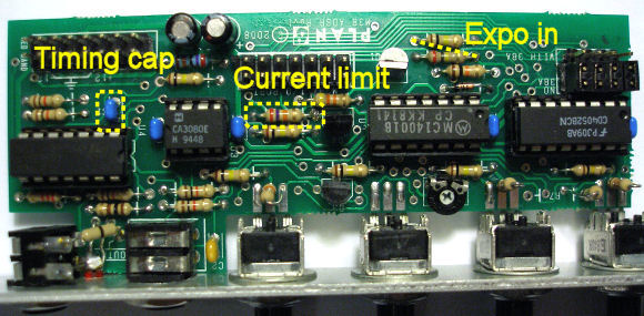
The modification. After some calculation and experimentation, as well as adding the missing resistor at a suitable value, I decided to increase the value of the main timing cap to 100nF (the standard fit appears to be 10nF), and halve the current-limiting resistor feeding the CA3080 OTA in order to double the maximum current output by the exponential converter. The extra resistor needs to be added at the input of the expo converter, down to ground—this photo shows the locations on the top of the board:
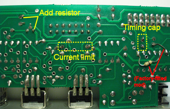
...and this photo the bottom:
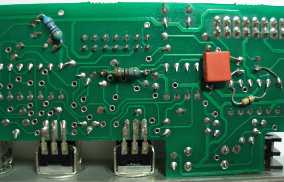
(Note the factory-fitted mod correcting an error in the PCB!) At first I tried a 3.3kΩ—this proved the feasibility of it all, but the envelope range was a bit restrictive, so I upped it to 4.7kΩ; I experimented with a few other combinations, but the 4.7k felt best. Here is a photo showing the extra bits added—the 4.7kΩ to ground, a second 27kΩ across the existing one to halve its value, and the additional 100nF cap across the existing 10nF one, so giving about 110n in total (of course the latter two could be replaced completely if desired):
The 4.7kΩ with 100nF gives a shortest envelope of a couple of milliseconds, and a longest of around a minute and a half:
(Note the difference in amplitude is because these measurements come from different scopes, and their calibrations are clearly a little in disagreement!) It should also be noted that since the voltages at the input of the expo converter are now changing by much smaller values, the problem of the large 'step up' at the beginning of the envelope in the original configuration has disappeared. Repeating the initial plot at the top of the page, of the attack time versus the attack wiper voltage, and we can now see that the complete sweep of the attack pot gives some useful effect (the original trace is again included, for comparison purposes)—the sweep is from a minimum attack time of about 750μs to about 14.5 seconds:
To adjust the trimpot: set all the pots fully counter-clockwise, including the trimpot—this will give the fastest envelope. Now turn the trimpot clockwise until the envelope just starts to slow down (probably best done on a scope if available, but feeding the envelope to a VCO will probably do as well). Setting the trimpot any further CCW will simply mean that the front-panel pot travel is wasted, so this method should give the biggest sweep of envelope times from fastest to slowest. Other combinations I tried were the new resistor at 6.8kΩ with a 68nF cap in parallel to the existing one. This gave a huge range: the quickest attack was then about 500μs, with the whole envelope about 3ms; the longest was long—I miscalculated how many readings I needed to make with my Picoscope so I couldn't capture the whole thing, but just the attack was about 25 minutes, and I abandoned the readings a few minutes later! Naturally enough these values suffer from the original problem (but perhaps to a much lesser extent), in that it was starting to get a little fiddly to get the pot positions just right. I also tried 5.6kΩ plus the 100nF cap—this gave a shortest envelope of around 3ms again, and the longest was around 10 minutes or so, and again it is clear that small pot movements end up giving quite largish changes to the envelope. Another thing of note perhaps is that the attack phase is always fairly linear. It should be possible to make it more log-like by increasing 100kΩ resistor 'R7' near the attack pot (it is standing up on its footprint due to another PCB error...)—this will of course lengthen all envelopes. Sustain voltage level behaviour: in most normal envelope generators we expect that once the peak of the envelope is reached at the end of attack, then the envelope would start falling away (we are in 'decay' after all!), often down to some (non-zero) 'sustain' level, where it remains until the gate is released. In the M38, the circuitry controlling the sustain level doesn't actually limit the sustain voltage to be below the peak reached at the end of attack (about 6V); consequently if the sustain pot is above about setting '6', then the sustain level is actually above the level of the (would be) peak at the end of attack, and so the envelope continues to rise even though we are nominally 'in decay'! The follwing set of traces illustrate the different envelopes generated as the sustain pot is set at '0', '2', '4' and so on, up to fully clockwise at '10':
Impact of pot law: my original assessment above, that changing the type of pots used in the module "would have left the problem substantially unresolved", was an unsubstantiated supposition based on my knowledge of the circuit topology, rather than any actual evidence. Following a brief exchange with Peter in late 2017, when he again put forward the view that the pot type was the cause of the M38's problems, I felt compelled to look at this again (for the sake of fairness and completeness) to gain a more objective view, as opposed to my subjective, intuition-based, previous statement. I was not about to start replacing pots on my unit and spend endless hours taking measurements, as SPICE simulation will do the job well enough: however, even doing it that way is not easy, as it requires running many transient analyses at different pot settings, then plotting the time for the envelope to reach a given point against each pot setting—fortunately SIMetrix has an inbuilt probing script which will do this last part automatically. However I did feel I needed a little more confidence that the simulation would provide reliable data that mimicks the real world, especially as the differences between the responses due to the different pot types might be slight, so I did a rough 'fit' of the simulation to the data I had measured for the attack times as plotted in the first graph on this page. Doing this by adjusting the trimpot setting within the simulation resulted in the green trace in the following plot, the red being the measured data:
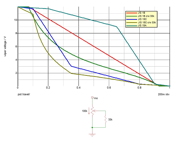
On the larger scale at the left it looked sufficiently close that I didn't feel the need to do anything further (for example running the simulation with the main integrator capacitor other than the nominal value, by measuring the actual value on the unit), and subsequent plots below do show identifiably different shapes due to the different pot law arrangements, so I felt this was good enough. (The smaller scale plot of the same segment on the right is roughly equivalent to the second plot on this page, showing how restricted the range of the envelope times is compared to the full range of the pot, and differences between the simulated and real data are more difficult to discern of course). Next up, the pot laws. It is my understanding that many popular pot manufacturers use the standard JIS (Japanese Industrial Standards) tapers for their pots, these being JIS 1B for B-type linear pots, JIS 15A for A-type log pots, and JIS 15C for C-type inverse (or reverse) log pots. It is a simple matter to model each of these in SPICE. The following graphic shows how the A, D and R pots of the M38 are configured, and how the wiper voltage varies as the pot is 'swept' from 0 (fully counter-clockwise) to 1 (fully clockwise) for the different pot types (Vcc is 12V!)—the arrow represents the direction of clockwise rotation. The resistor from wiper to ground is not included when making all the plots, only for the two annotated 'c/w 33k'—it is a standard trick which can be used to distort the pot curve to make it more closely resemble another, used to good effect in the M38 by noting that the original fitment of a B pot with resistor, 'B c/w 33k', is a similar shape to the 'C' taper (green vs. blue). Note that because of the way the pots are wired, these plots may be mirrored from the usual shapes seen on pot datasheets; this sense of the inversion of the plot position with respect to wiper voltage (greater rotation decreases the voltage) is also the reason the curves of attack times below, referenced to pot position, are flipped with respect to the measured shapes at the top of the page, which are referenced to the wiper voltage.
So we now run the simulation for each of these pot types/resistor arrangements, in order to obtain some curves for comparison. The simulation circuit was effectively hard-wired to give just the attack phase, with multiple transient runs performed, stepping the attack pot by just one thousandth of its total travel for each run, across the range which produces usable results, fairly arbitrarily defined as giving an attack time from about 2ms up to about 8 seconds. This gives a family of curves which look like this (in this case 61 steps, for the standard M38 arrangement of B pot c/w 33kΩ resistor):
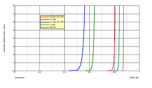
The actual envelope on a real unit switches from attack to decay at about 6V, so in effect we need to draw a line at 6V across all the curves, and pick off the time where the envelope at each pot setting crosses the 6V line, and plot the resulting times against the pot setting—this is the bit that thankfully SIMetrix has an automated script for, and doing so for each pot/resistor combination above, gives the following curves:
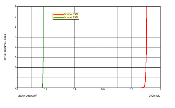
(Note I made no attempt to adjust the trimpot setting in order to place the curves at any particular point—since the circuit consists of several resistors, including the pot itself, it is no surprise that different pot types do affect the point where all the action occurs.) So what do we see? The B law pot on its own (cyan) has a very sharp knee to it, which would make it hard to control; adding the 33kΩ resistor, as the standard M38 configuration, rounds the curve out somewhat (the red trace), and note this shape is similar to the C pot (without resistor), the green trace—this is no surprise as adding the resistor to the B pot brings the two pot responses quite close, as already noted above. Thus there would be little point in removing the B pot and resistor and replacing with a C pot alone. However, if the resistor were left in place, and the pot changed to a C type, due to the additional distortion of the pot curve there would be an appreciably greater spread of the useful pot travel, the blue trace, which is perhaps giving a usable range of twice that of the standard arrangement. Finally, for completeness, I included an A type pot (brown trace), and we can see this is going in completely the wrong direction, and would make it very hard to control the envelope, due to the switch from short times to a near-vertical line for longer ones. And finally, again for completeness, the following trace shows the effect of adjusting the trimpot on the shape of the curve: this is for the the standard arrangement of B pot c/w 33kΩ resistor, with the trimpot at 15% and 85% of full travel, showing that there is some effect on the shape of the curve (and again this isn't much of a surprise, as noted before, the whole set-up consists of a bunch of resistors interacting in many ways):
I couldn't be bothered to run comparison plots of, say, the C pot plus 33kΩ arrangement at both high and low trimpot settings, as it looks to me that the gains to the usable range of pot travel, when compared to the resistor mod outlined further up the page, really don't look like they would be worth it. One could also investigate using one of the more extreme type C pot laws that exist, but then a simple drop-in replacement of an off-the-shelf pot with the same form factor as the existing pot might be rather difficult to find. [Page last updated: 28 Jan 2018] |