![]()
|
|
Personal web pages ofTim Stinchcombe |
EDP Gnat Synthesizer SchematicsI originally bought one of these out of idle curiosity - having read all about the Wasp and its use of digital inverters in the analogue section, I couldn't resist buying a Gnat (a 'Special' in fact) when the opportunity arose. It was sold as non-working, and after replacing a few chips, I got it working. On acquiring a Wasp, and then a second Gnat, it became clear there were differences between both the Gnat and the Wasp, and between the Gnats themselves. Nothing for it to but to reverse-engineer the whole thing, and have a look-see myself! The schematics are only hand-drawn, and I make absolutely no guarantees to their correctness whatsoever (more notes follow):
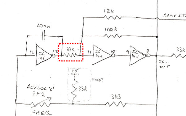
(All credits go to Adrian Wagner and Chris Huggett, who were responsible for the original conceptualization and design of the Wasp family of synthesizers. It is unknown if the rights etc. to the circuits rest with any particular individual or organisation, but Adrian Wagner certainly gave his permission for me to place these schematics here.) Most of the logic is 4000 series CMOS, and I've not necessarily shown either what the actual device is, nor the ground and power pins (unless I've wanted to check, for the less common ones, that I have accounted for all the pins). (Device types might be readable on the photo below.) All the OTAs are CA3080; all transistors are PNP BC214L; I've attempted to draw a 'standardish' symbol for the 'Norton amps', which are LM3900; there appear to be some tantalum caps on the board, but I've made no attempt to establish their polarity. I'm happy to hear of any mistakes I've made, but initially I'll just list them here, as scanning the whole lot was quite an ordeal in itself (and unfortunately I don't seem to have any control on the page orientation, which is why some are portrait, some landscape). Errata: (17 Dec 2015) A 33kΩ resistor between pins 11 and 12 in the LFO circuit got left out! There is no silkscreen on the PCB identifying each device, thus as an aid to tracing the circuit I scanned the PCB twice on each side, and joined the images. I originally roughly annotated this with each chip's function, but shortly after posting it I received a copy of the 'test instructions' (see below) with a sketch of the IC locations, and this has enabled me to add the actual IC reference designators, presumably as used on the original schematics (click the image for the full-size version):
In comparison to the Wasp (for which Elby Designs, who make a clone of the Wasp, have a nice tidied-up set of the schematics here), they seem to have stuck to the same general ideas, but the implementation in many places is quite different: in most of the analogue side - VCA, filter, envelopes etc. - there are lots of differences; on the digital side, the keyboard scanning is quite different, but does achieve the same end. One of the Gnats I have (out of three now!), has what appear to be a couple of mods to the LFO circuit, which I've indicated on the schematics - I've not really attempted to reconcile these yet with the obvious difference in sound they make. Other useful EDP stuff and linksJPEG scans of the original Wasp schematics can be found at synthdiy.com along with some Test Instructions for the Wasp. Here is a similar document of Gnat Test Instructions:
Amongst other useful things in here, this contains the patterns for the 40103 note division presetting, which may prove useful for troubleshooting. Update Nov 2023: the 8-page Wasp manual linked in the next paragraph obviously isn't the only Wasp 'owner's manual' out there, as I have just been sent a nice scan of another version, which has over three times as many pages! It also contains a good deal more information on using a Spider sequencer too. I have a fairly tatty Wasp user manual that I have scanned in black and white; and for a bit of fun, here are the front and back covers in colour, for the full garish, yellow-black Wasp effect! (1Meg file):
This is a scan of the Gnat user manual (3.5Meg file):
—the originals look to be a photocopy of a heavily damaged and stained document, hence all the text bleed-through etc. To make it sensible it had to be scanned 'greyscale', and even at 200dpi it is still a 3.5Meg file. ('Frightened Helicopter' patch, hmmm...) And here we have a clearly original Spider schematic!:
Update Nov 2023: the Wasp manual newly uploaded above also contains a load of information on using the Spider. Last but not least, a copy of the Spider user manual, which is rather terse, but looks to be original:
Update Nov 2015: following an enquiry about the Spider's operation, I noticed that the manual mentions three 'presets' on the side of the unit, and yet the schematic clearly only shows two. On tracing out the circuit in my unit around the 'missing' one, it became apparent that the above schematic differs from reality (at least for my unit!):
This is the 'CV out' part of the circuit, at top-left of the schematic, processing the voltage output from the DAC IC, ZN426—the extra trimpot allows a DC offset to be subtracted from the DAC voltage (so in a sense this trimpot is better called 'range', and the other on the following op amp is closer to 'scale', as all it does is multiply the signal from between 1 and 3). Note also that the pin-out of the first op amp shows the section used in the chip is different from that shown on the full schematic—I didn't check the rest of the circuit to see how consistent the rest of it might be! [Page last updated: 13 Nov 2023] |


