![]()
|
|
Personal web pages ofTim Stinchcombe |
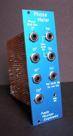
Phase Meter and Phase Shift Oscillator
I wanted some kind of phase measuring device, so that as well as plotting frequency responses of filters, I could plot their phase responses too. Eventually I found an old patent which fitted the bill: US PTO 4,246,497, 'Phase Measuring Circuit', KD Lawson & L Brown. It is a clever arrangement of flip-flops, XOR gates and analogue switches, which produces positive and negative voltages representing a full ±180° range. It wasn't too difficult to adapt the circuit from the patent, and the addition of a simple Sallen-Key lowpass filter gives a reading which is responsive, yet steady enough, for my purposes. To be able to check that the phase meter was doing something reasonable, I needed some waveforms with a known phase relationship. A simple phase-shift oscillator seemed to be the answer, and this was an interesting enterprise in its own right: the initial idea of 4 RC sections plus an inverting amp (4 x 45° + 180° = 360°) quickly turned into 3 sections plus an inverting integrator (giving a 225° shift), to which some simple diode-limiting could be applied to control the amplitude - here's the end result. With an R of 10kΩ and a C of 15nF, the design frequency works out to be 1061Hz; in actuality, it oscillates at around 1022Hz. I was also surprised, considering how crude the amplitude limiting with the diodes is, just how good the sine waves are that it produces - here is a composite of all four phases, triggered at the same point:
The red trace is the output from the integrator: this contains the amplitude-limiting diodes, so perhaps it is no surprise that it is the most distorted waveshape, with a little asymmetry at the peaks just noticeable. Even so, this spectrum plot from my Picoscope reckons less than 1% total harmonic distortion:
Here is the spectrum from the 90° phase (the green trace), which is the least distorted shape, at just over 0.2%:
And finally, a Lissajou figure from the 45° and 135° phases, which gives the closest to a circle - the phases are within a degree or so, which when combined with the accuracy of the phase meter of about the same magnitude, should be adequate for my purposes:
[Page last updated: 14 Dec 2009] |